

PE310G4BPI71 Bypass Networking Server Adapters
-
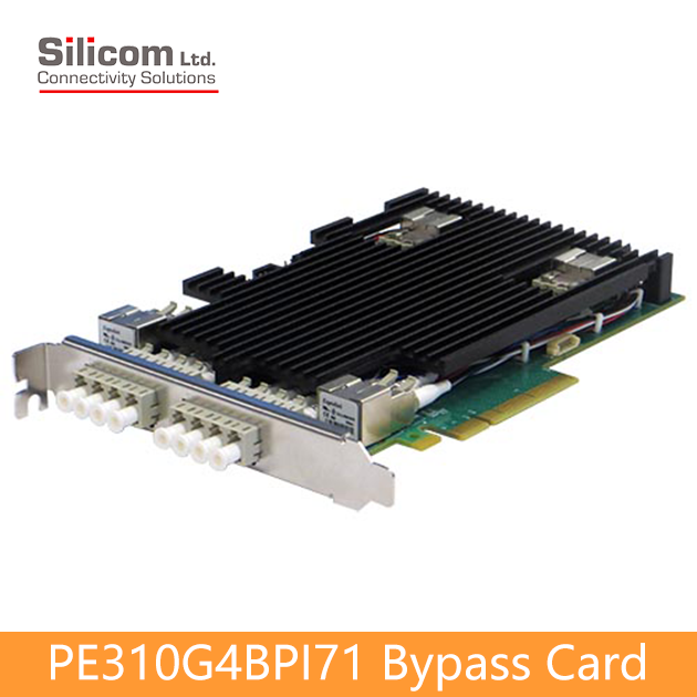
PE310G4BPI71 Bypass Card
Quad Port Fiber 10 Gigabit Ethernet PCI Express Bypass Server Adapter Intel® XL710BM1 Based
Silicom’s quad port fiber 10Gigabit Ethernet Cloud Computer Bypass server adapter is a PCI-Express X8 network interface card that contains four 10 Gigabit Ethernet ports on a PCI-E adapter. The Silicom’s quad port fiber 10 Gigabit Ethernet Cloud Computer Bypass server adapter is targeted to inline network system that maintains network connectivity when system fails. Silicom’s quad port fiber 10 Gigabit Ethernet Cloud Computer Bypass server adapter supports Normal, Bypass and Disconnect modes. In Normal mode, the ports are independent interfaces. In Bypass mode, all packets received from one port are transmitted to the adjacent port. In Disconnect mode, the adapter simulates switch / rout cable disconnection. Silicom’s quad port fiber 10 Gigabit Ethernet Bypass server adapter can Bypass or disconnect its Ethernet ports on a host system failure, power off, or upon software request.
In Bypass mode, the connections of the Ethernet ports are disconnected from the system and switched over to the other port to create a crossed connection loop-back between the Ethernet ports. Hence, in bypass mode all packets received from one port are transmitted to the adjacent port and vice versa. This feature enables to bypass a failed system and provides maximum up time for the network. Silicom’s quad port fiber 10 Gigabit Ethernet Bypass server adapter includes an on board WDT (Watch Dog Timer) controller. The adapter’s software drivers or software application can write commands to the on board WDT controller. The adapter’s software drivers, WDT controller and the Bypass circuitry provide an interface that control and manage the mode of the adapter. The Silicom 10 Gigabit Ethernet Bypass server adapters are based on Intel XL710 Ethernet controllers.
-
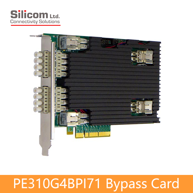
PE310G4BPI71 Bypass Card
Quad Port Fiber 10 Gigabit Ethernet PCI Express Bypass Server Adapter Intel® XL710BM1 Based
Bypass / Disconnect:
‧Bypass / Disconnect Ethernet ports on Power Fail, System Hangs or Software Application Hangs
‧Software programmable Bypass, Disconnect or Normal Mode
‧On Board Watch Dog Timer (WDT) Controller
‧Software programmable time out interval
‧Software Programmable WDT Enable / Disable counter
‧Software programmable Bypass Capability Enable / Disable
‧Software Programmable Disconnect Capability Enable / Disable
‧Software Programmable mode (Bypass, Normal or Disconnect mode) at Power up
‧Software Programmable mode (Bypass, Normal mode) at Power off
‧Independent Bypass operation in every two ports
‧Emulates standard NICSR: Fiber 10 Gigabit Ethernet 10GBASE-SR:
‧10 Gigabit Fiber Ethernet port supports 10GBASE-SR (850nm LAN PHY)
‧MM 850nm 10GBASE-SW/SR, Duplex Low Profile Transceiver-LR: Fiber 10 Gigabit Ethernet 10GBASE-LR:
‧10 Gigabit Fiber Ethernet port supports 10GBASE-LR (1310nm LAN PHY)
‧SM 1310nm 10GBASE-LW/LR, Duplex Low Profile TransceiverPerformance Features:
‧Support for jumbo frame up to 9.5KB
‧Flow control support
‧Priority Flow Control (draft IEEE 802.1Qbb)
‧Enhanced Transmission Selection (draft IEEE802.1az)
‧Statistics management and RMON
‧802.1q VLAN support
‧DCB/DCB-X support
‧Message Signal interrupts (MSI-X)
‧Storage – Enabling competitive performance with native OS intelligent offload solutions, including NAS, iSCSI and FCoEHost Interface:
‧PCI Express X8 lanes
‧Support PCI Express Base Specification 3.0 (8GT/s) -
PE310G4BPI71 Bypass Card
Quad Port Fiber 10 Gigabit Ethernet PCI Express Bypass Server Adapter Intel® XL710BM1 Based
Bypass Specifications
WDT Interval(Software Programmble) 3,276,800 mSec (3,276.8 Sec): Maximum
100 mSec ( 0.1 Sec) : Minimum
WDT Interval = (2^wdt_interval_parameter)*(0.1) sec. wdt_interval_parameter: { Valid Range: 0-15}– SR: Fiber 10GBASE-SR Technical Specifications
IEEE Standard / Network topology: Fiber 10 Gigabit Ethernet, 10GBase-SR (850nm) Data Transfer Rate: 10.3125GBd Cables and Operating distance: Up to: Multimode fiber:
62.5um, 160MHz/Km 13m*
62.5um, (OM1)200MHz/Km 16.5m *
50um, 400MHz/Km 66m
50um, (OM2)500 MHz/Km 82m
50um, (OM3)2000MHz/Km 300m
* Defined as half as the distance as specified in the optical transceiverOptical Output Power: Normal Mode (Bypass Off): Minimum: -7.3 dBm Optical Receive Sensitivity: Normal Mode (Bypass Off) Maximum: -11 dBm Insertion Loss: Bypass Mode: Insertion loss Maximum 1.6 dB – LR: Fiber 10GBASE-LR Technical Specifications
IEEE Standard / Network topology: Fiber 10Gigabit Ethernet, 10GBASE-LR (1310nm) Data Transfer Rate: 10.3125GBd Cables and Operating distance: Up to: Single-Mode: 5Km at 9um *
* Defined as half as the distance as specified in the optical transceiverOptical Output Power: Normal Mode (Bypass Off):Minimum: -5.2 dBm Optical Receive Sensitivity: Normal Mode (Bypass Off)Maximum: -12.6 dBm Insertion Loss: Bypass Mode: Insertion loss (Optical Power attenuation between TX to RX) (LC- fiber- switch- LC) Typical: TBD dB (From RX to TX) Maximum 0.5 dB Operating Systems Support
Operating system support: Linux
Windows
VMware
FreeBSDGeneral Technical Specifications
Interface Standard: PCI-Express Base Specification Revision 3.0 (8 GTs) Board Size: Standard height short add-in card 167.64mm X 109.1 mm (6.6”X 4.296”) PCI Express Card Type: X8 Lane PCI Express Voltage: +12V +- 8% PCI Connector: Gold Finger: X8 Lane Controller: Intel XL710 Holder: Metal Bracket I/O LC located on internal bracket Power Consumption(SR): 6.24 W, 0.52 A at 12V: Typical all ports operate at 10Gb/s
5.4 W, 0.45 A at 12V: Typical Bypass Mode
5.4 W, 0.45 A at 12V: Typical Disconnect Mode
6 W, 0.5 A at 12V: Typical No link at all portsPower Consumption(LR): 6.36 W, 0.53 A at 12V: Typical all ports operate at 10Gb/s
5.52 W, 0.46 A at 12V: Typical Bypass Mode
5.52 W, 0.46 A at 12V: Typical Disconnect Mode
6.12 W 0.51 A at 12V: Typical No link at all portsOperating Humidity: 0%–90%, non-condensing Operating Temperature: 0°C – 45°C (32°F – 113°F) Storage: -40°C–65°C (-40°F–149°F) EMC Certifications FCC 47CFR Part 15:2013, Subpart B Class B
Conducted emissions
Radiated emissions
EN 55022: 2010, Class B
Conducted disturbance at mains terminals
Conducted disturbance at telecommunication port
Radiated disturbance
EN 61000-3-2: 2006+A1(09)+A2(09)
Harmonic current emissions
EN 61000-3-3: 2008
Voltage fluctuations and flicker
EN 55024: 2010
Immunity to electrostatic discharge (ESD)
Radiated immunity to radio frequency electromagnetic field
Conducted immunity to electrical fast transients / bursts (EFT/ B)
Conducted immunity to voltage surges
Conducted immunity to disturbances induced by radio frequency field
Conducted immunity to voltage dips and short interruptionsMTBF*: 81 (Years)
** According to Telcordia SR-332 Issue 3. Environmental condition – GB (Ground, Fixed, and Controlled). Ambient temperature 40°CLEDs:
LEDs: (1) LED per port
LED: SPD/ACT:
Blinks on activity 10Gbps (Blue)
(1) Bi- color LED per segment (2 ports):
Off on Normal Mode
Turns on Bypass Mode (Green)
/ Turns on Disconnect Mode (Yellow)LEDs location: LEDs are located on the PCB, visible via holes in the metal bracket.
Each 2 Blue 10G SPD-ACT LEDs (1 LED per port) are located under their own LC connector port.
(Each LC contains 2 ports).
The Yellow/Green for Disconnect and Bypass LED is located between the 2 ports in each segment – in the middle under each LCConnectors: (2) LC Functional Description
Normal/Bypass/Disconnect mode
Silicom’s Quad Port Bypass adapter supports Normal, Bypass and Disconnect modes. In Normal mode, the ports are independent interfaces (see Figure 1: Normal mode, one Bypass pair is illustrated).
Normal mode
In Normal mode, the ports are independent interfaces (see Figure 1: Normal mode, one Bypass pair is illustrated).
Figure 1: Normal Mode Functional Block Diagram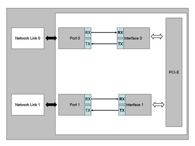
Bypass mode
In Bypass mode, the connections of the Ethernet network ports are disconnected from the interfaces and switched over to the other port to create a crossed connection loop-back between the Ethernet ports. The connections of the interfaces are left unconnected. (See Figure 2: one Bypass pair illustrated)
Figure 2: Bypass Mode Functional Block Diagram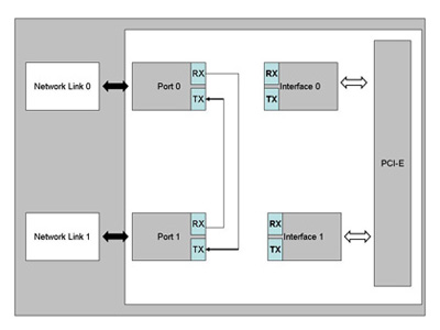
Disconnect mode
In Disconnect mode, the transmit connections of the Ethernet network ports are Disconnected from the interfaces. (See Figure 3: one Bypass pair illustrated)
Figure 3: Disconnect Mode Functional Block Diagram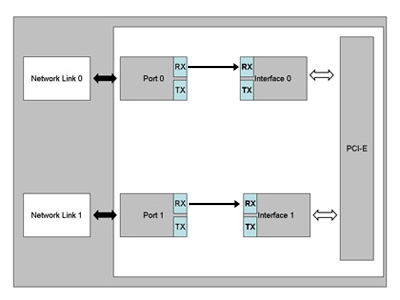
Silicom Bypass server adapters include an on board Controller that can Bypass the Ethernet ports on host system failure like Power Off, System hangs or software application hangs. The software programmable Watch Dog Timer (WDT) Controller detects a host system fails and it will Bypass automatically the Ethernet ports after programmable time out interval. The WDT Controller can be software programmable enabled or disabled.
Silicom Bypass server adapters support software programmable to select Bypass or Normal mode. In Normal mode, the ports of the adapters remain independently operational.
The drivers of the adapters and the Bypass circuitry provides an interface that control and management the mode of the adapter. The adapter software driver or software application can writes commands to the on board controller. The on board controller processes the commands and activates the bypass circuitry accordingly.
After power up the default mode of the adapter is to be in Bypass mode. After driver is loaded, the adapter software driver or application can set the card to a Normal mode. After the Host system issues reset, setting of Bypass controller and circuitry are reserved.
Silicom Bypass server adapters support Disable Bypass Capability; hence, if those adapters receive Disable Bypass Capability command, the adapter does not Bypass its Ethernet ports, in this state the four Ethernet ports are independent. The Disable Bypass Capability state is reserved also after power off. This feature enables to emulate a standard NIC.
Silicom Bypass server adapters can be set to Bypass or Normal mode at power up. This setting programmable and is reserved also after power off. -
PE310G4BPI71 Bypass Card
Quad Port Fiber 10 Gigabit Ethernet PCI Express Bypass Server Adapter Intel® XL710BM1 Based
P/N
Description
Notes:
PE310G4BPI71-SR Quad Port Fiber (SR) 10 Gigabit Ethernet PCI Express Bypass Server Adapter X8 Gen 3, Based on Intel XL710, on board support for Fiber SR, RoHS compliant PE310G4BPI71-LR Quad Port Fiber (LR) 10 Gigabit Ethernet PCI Express Bypass Server Adapter X8 Gen 3, Based on Intel XL710, on board support for Fiber LR, RoHS compliant 1V6
-
Product Description
PE310G4BPI71 Bypass Card
Quad Port Fiber 10 Gigabit Ethernet PCI Express Bypass Server Adapter Intel® XL710BM1 Based
Silicom’s quad port fiber 10Gigabit Ethernet Cloud Computer Bypass server adapter is a PCI-Express X8 network interface card that contains four 10 Gigabit Ethernet ports on a PCI-E adapter. The Silicom’s quad port fiber 10 Gigabit Ethernet Cloud Computer Bypass server adapter is targeted to inline network system that maintains network connectivity when system fails. Silicom’s quad port fiber 10 Gigabit Ethernet Cloud Computer Bypass server adapter supports Normal, Bypass and Disconnect modes. In Normal mode, the ports are independent interfaces. In Bypass mode, all packets received from one port are transmitted to the adjacent port. In Disconnect mode, the adapter simulates switch / rout cable disconnection. Silicom’s quad port fiber 10 Gigabit Ethernet Bypass server adapter can Bypass or disconnect its Ethernet ports on a host system failure, power off, or upon software request.In Bypass mode, the connections of the Ethernet ports are disconnected from the system and switched over to the other port to create a crossed connection loop-back between the Ethernet ports. Hence, in bypass mode all packets received from one port are transmitted to the adjacent port and vice versa. This feature enables to bypass a failed system and provides maximum up time for the network. Silicom’s quad port fiber 10 Gigabit Ethernet Bypass server adapter includes an on board WDT (Watch Dog Timer) controller. The adapter’s software drivers or software application can write commands to the on board WDT controller. The adapter’s software drivers, WDT controller and the Bypass circuitry provide an interface that control and manage the mode of the adapter. The Silicom 10 Gigabit Ethernet Bypass server adapters are based on Intel XL710 Ethernet controllers.
-
Features
PE310G4BPI71 Bypass Card
Quad Port Fiber 10 Gigabit Ethernet PCI Express Bypass Server Adapter Intel® XL710BM1 Based
Bypass / Disconnect:
‧Bypass / Disconnect Ethernet ports on Power Fail, System Hangs or Software Application Hangs
‧Software programmable Bypass, Disconnect or Normal Mode
‧On Board Watch Dog Timer (WDT) Controller
‧Software programmable time out interval
‧Software Programmable WDT Enable / Disable counter
‧Software programmable Bypass Capability Enable / Disable
‧Software Programmable Disconnect Capability Enable / Disable
‧Software Programmable mode (Bypass, Normal or Disconnect mode) at Power up
‧Software Programmable mode (Bypass, Normal mode) at Power off
‧Independent Bypass operation in every two ports
‧Emulates standard NICSR: Fiber 10 Gigabit Ethernet 10GBASE-SR:
‧10 Gigabit Fiber Ethernet port supports 10GBASE-SR (850nm LAN PHY)
‧MM 850nm 10GBASE-SW/SR, Duplex Low Profile Transceiver-LR: Fiber 10 Gigabit Ethernet 10GBASE-LR:
‧10 Gigabit Fiber Ethernet port supports 10GBASE-LR (1310nm LAN PHY)
‧SM 1310nm 10GBASE-LW/LR, Duplex Low Profile TransceiverPerformance Features:
‧Support for jumbo frame up to 9.5KB
‧Flow control support
‧Priority Flow Control (draft IEEE 802.1Qbb)
‧Enhanced Transmission Selection (draft IEEE802.1az)
‧Statistics management and RMON
‧802.1q VLAN support
‧DCB/DCB-X support
‧Message Signal interrupts (MSI-X)
‧Storage – Enabling competitive performance with native OS intelligent offload solutions, including NAS, iSCSI and FCoEHost Interface:
‧PCI Express X8 lanes
‧Support PCI Express Base Specification 3.0 (8GT/s) -
Specifications
PE310G4BPI71 Bypass Card
Quad Port Fiber 10 Gigabit Ethernet PCI Express Bypass Server Adapter Intel® XL710BM1 Based
Bypass Specifications
WDT Interval(Software Programmble) 3,276,800 mSec (3,276.8 Sec): Maximum
100 mSec ( 0.1 Sec) : Minimum
WDT Interval = (2^wdt_interval_parameter)*(0.1) sec. wdt_interval_parameter: { Valid Range: 0-15}– SR: Fiber 10GBASE-SR Technical Specifications
IEEE Standard / Network topology: Fiber 10 Gigabit Ethernet, 10GBase-SR (850nm) Data Transfer Rate: 10.3125GBd Cables and Operating distance: Up to: Multimode fiber:
62.5um, 160MHz/Km 13m*
62.5um, (OM1)200MHz/Km 16.5m *
50um, 400MHz/Km 66m
50um, (OM2)500 MHz/Km 82m
50um, (OM3)2000MHz/Km 300m
* Defined as half as the distance as specified in the optical transceiverOptical Output Power: Normal Mode (Bypass Off): Minimum: -7.3 dBm Optical Receive Sensitivity: Normal Mode (Bypass Off) Maximum: -11 dBm Insertion Loss: Bypass Mode: Insertion loss Maximum 1.6 dB – LR: Fiber 10GBASE-LR Technical Specifications
IEEE Standard / Network topology: Fiber 10Gigabit Ethernet, 10GBASE-LR (1310nm) Data Transfer Rate: 10.3125GBd Cables and Operating distance: Up to: Single-Mode: 5Km at 9um *
* Defined as half as the distance as specified in the optical transceiverOptical Output Power: Normal Mode (Bypass Off):Minimum: -5.2 dBm Optical Receive Sensitivity: Normal Mode (Bypass Off)Maximum: -12.6 dBm Insertion Loss: Bypass Mode: Insertion loss (Optical Power attenuation between TX to RX) (LC- fiber- switch- LC) Typical: TBD dB (From RX to TX) Maximum 0.5 dB Operating Systems Support
Operating system support: Linux
Windows
VMware
FreeBSDGeneral Technical Specifications
Interface Standard: PCI-Express Base Specification Revision 3.0 (8 GTs) Board Size: Standard height short add-in card 167.64mm X 109.1 mm (6.6”X 4.296”) PCI Express Card Type: X8 Lane PCI Express Voltage: +12V +- 8% PCI Connector: Gold Finger: X8 Lane Controller: Intel XL710 Holder: Metal Bracket I/O LC located on internal bracket Power Consumption(SR): 6.24 W, 0.52 A at 12V: Typical all ports operate at 10Gb/s
5.4 W, 0.45 A at 12V: Typical Bypass Mode
5.4 W, 0.45 A at 12V: Typical Disconnect Mode
6 W, 0.5 A at 12V: Typical No link at all portsPower Consumption(LR): 6.36 W, 0.53 A at 12V: Typical all ports operate at 10Gb/s
5.52 W, 0.46 A at 12V: Typical Bypass Mode
5.52 W, 0.46 A at 12V: Typical Disconnect Mode
6.12 W 0.51 A at 12V: Typical No link at all portsOperating Humidity: 0%–90%, non-condensing Operating Temperature: 0°C – 45°C (32°F – 113°F) Storage: -40°C–65°C (-40°F–149°F) EMC Certifications FCC 47CFR Part 15:2013, Subpart B Class B
Conducted emissions
Radiated emissions
EN 55022: 2010, Class B
Conducted disturbance at mains terminals
Conducted disturbance at telecommunication port
Radiated disturbance
EN 61000-3-2: 2006+A1(09)+A2(09)
Harmonic current emissions
EN 61000-3-3: 2008
Voltage fluctuations and flicker
EN 55024: 2010
Immunity to electrostatic discharge (ESD)
Radiated immunity to radio frequency electromagnetic field
Conducted immunity to electrical fast transients / bursts (EFT/ B)
Conducted immunity to voltage surges
Conducted immunity to disturbances induced by radio frequency field
Conducted immunity to voltage dips and short interruptionsMTBF*: 81 (Years)
** According to Telcordia SR-332 Issue 3. Environmental condition – GB (Ground, Fixed, and Controlled). Ambient temperature 40°CLEDs:
LEDs: (1) LED per port
LED: SPD/ACT:
Blinks on activity 10Gbps (Blue)
(1) Bi- color LED per segment (2 ports):
Off on Normal Mode
Turns on Bypass Mode (Green)
/ Turns on Disconnect Mode (Yellow)LEDs location: LEDs are located on the PCB, visible via holes in the metal bracket.
Each 2 Blue 10G SPD-ACT LEDs (1 LED per port) are located under their own LC connector port.
(Each LC contains 2 ports).
The Yellow/Green for Disconnect and Bypass LED is located between the 2 ports in each segment – in the middle under each LCConnectors: (2) LC Functional Description
Normal/Bypass/Disconnect mode
Silicom’s Quad Port Bypass adapter supports Normal, Bypass and Disconnect modes. In Normal mode, the ports are independent interfaces (see Figure 1: Normal mode, one Bypass pair is illustrated).
Normal mode
In Normal mode, the ports are independent interfaces (see Figure 1: Normal mode, one Bypass pair is illustrated).
Figure 1: Normal Mode Functional Block Diagram
Bypass mode
In Bypass mode, the connections of the Ethernet network ports are disconnected from the interfaces and switched over to the other port to create a crossed connection loop-back between the Ethernet ports. The connections of the interfaces are left unconnected. (See Figure 2: one Bypass pair illustrated)
Figure 2: Bypass Mode Functional Block Diagram
Disconnect mode
In Disconnect mode, the transmit connections of the Ethernet network ports are Disconnected from the interfaces. (See Figure 3: one Bypass pair illustrated)
Figure 3: Disconnect Mode Functional Block DiagramSilicom Bypass server adapters include an on board Controller that can Bypass the Ethernet ports on host system failure like Power Off, System hangs or software application hangs. The software programmable Watch Dog Timer (WDT) Controller detects a host system fails and it will Bypass automatically the Ethernet ports after programmable time out interval. The WDT Controller can be software programmable enabled or disabled.
Silicom Bypass server adapters support software programmable to select Bypass or Normal mode. In Normal mode, the ports of the adapters remain independently operational.
The drivers of the adapters and the Bypass circuitry provides an interface that control and management the mode of the adapter. The adapter software driver or software application can writes commands to the on board controller. The on board controller processes the commands and activates the bypass circuitry accordingly.
After power up the default mode of the adapter is to be in Bypass mode. After driver is loaded, the adapter software driver or application can set the card to a Normal mode. After the Host system issues reset, setting of Bypass controller and circuitry are reserved.
Silicom Bypass server adapters support Disable Bypass Capability; hence, if those adapters receive Disable Bypass Capability command, the adapter does not Bypass its Ethernet ports, in this state the four Ethernet ports are independent. The Disable Bypass Capability state is reserved also after power off. This feature enables to emulate a standard NIC.
Silicom Bypass server adapters can be set to Bypass or Normal mode at power up. This setting programmable and is reserved also after power off. -
Ordering Info
PE310G4BPI71 Bypass Card
Quad Port Fiber 10 Gigabit Ethernet PCI Express Bypass Server Adapter Intel® XL710BM1 Based
P/N
Description
Notes:
PE310G4BPI71-SR Quad Port Fiber (SR) 10 Gigabit Ethernet PCI Express Bypass Server Adapter X8 Gen 3, Based on Intel XL710, on board support for Fiber SR, RoHS compliant PE310G4BPI71-LR Quad Port Fiber (LR) 10 Gigabit Ethernet PCI Express Bypass Server Adapter X8 Gen 3, Based on Intel XL710, on board support for Fiber LR, RoHS compliant 1V6